Elanco Animal Health Incorporated is an American pharmaceutical company which produces medicines and vaccinations for pets and livestock. We undertook this project for them With Bayer Animal Health, which was acquired by Elanco.
Project Description
For this research and development project we developed a smart, IoT-capable Small Hive Beetle (SHB) trap that fits inside a standard Langstroth hive. Additionally, the proposed device counted the number of SHB entering the trap via gates and reported the count wirelessly. In addition to recording the SHB presence, the trap killed SHB via a brief high-voltage shock. The device provided:
- A time-indexed log of trap entrance activity for effective monitoring
- A high-voltage trap
- A wireless reporting mechanism
- A long-term power supply
- An enclosure that integrated with existing standard beekeeping equipment
- An enclosure that selectively excludes honeybees from the trap and kills SHB
- A user-interface
What We Did
Our team was comprised of expert engineers with specialties in each of the following disciplines:
- Mechanical Engineering
- Electrical Engineering (Software)
- Electrical Engineering (Hardware)
- Instrumentation and Control systems
- Internet of Things
- Embedded Systems
- Project Management
- Animal Husbandry & Livestock Expertise (Beekeeping)
Over the course of this special research and development project, we touched on these core competencies:
- Research & Development
- Rapid Prototyping & Manufacturing
- Electronics
- Internet of Things
- AgriTech
Design Description
Overview
As illustrated below, the SHB Smart Trap (Shown in white plastic), replaces one of the side bars of a standard Langstroth deep frame. The cross-sectional profile of the trap is identical to the standard side bar shown on the left side of the frame. This enclosure design requires no modification of the wooden frame components.
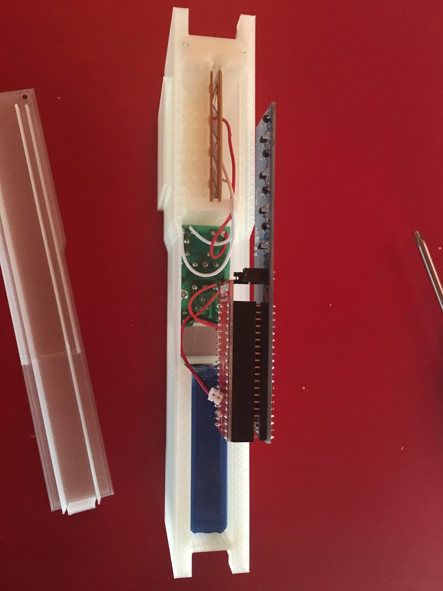
The smart SHB Trap is comprised of the following subsystems:
- The enclosure
- The detection system
- The high-voltage trap
- The power system
- The microcontroller
- Data-logging webserver
Prototype
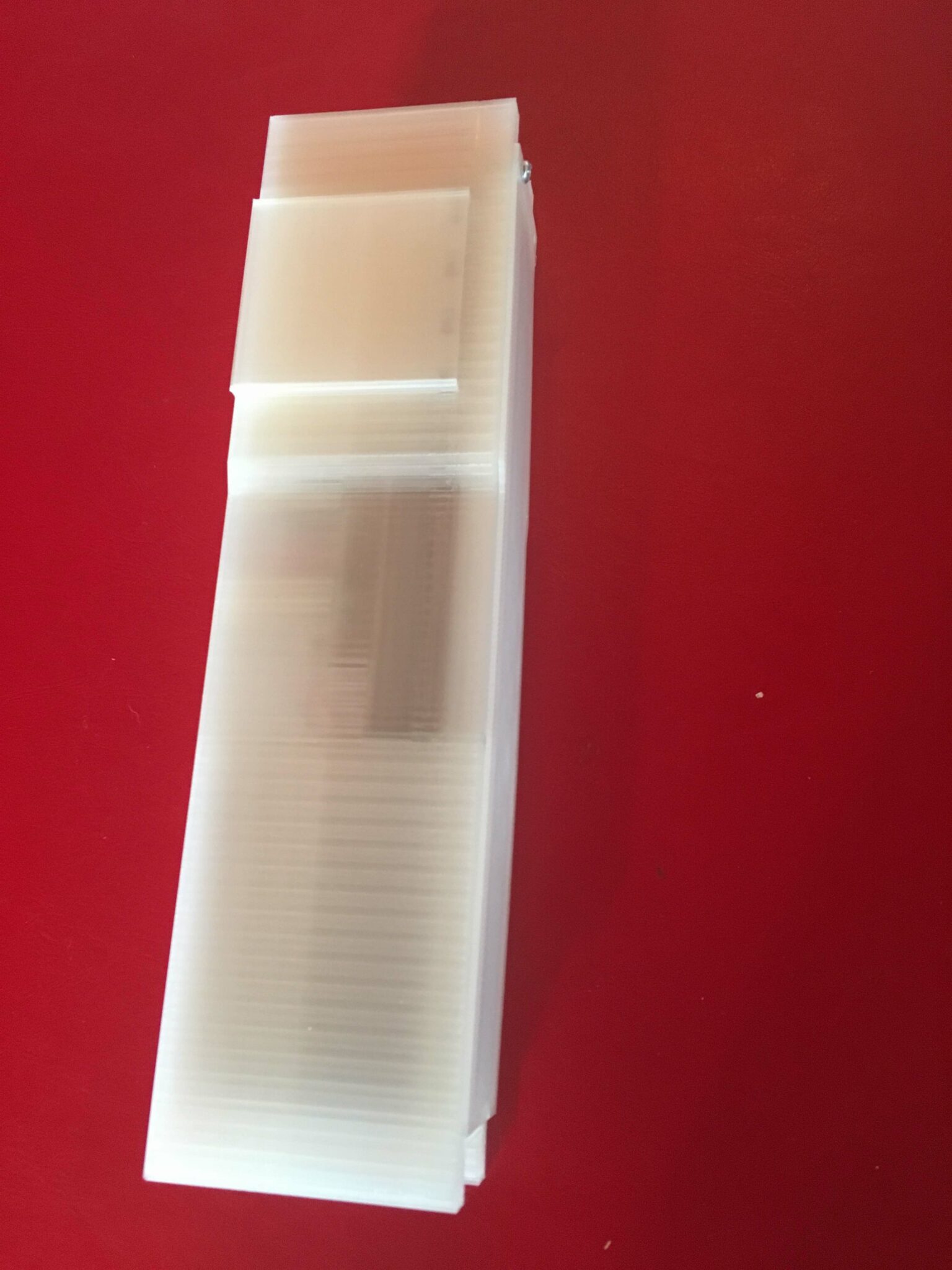
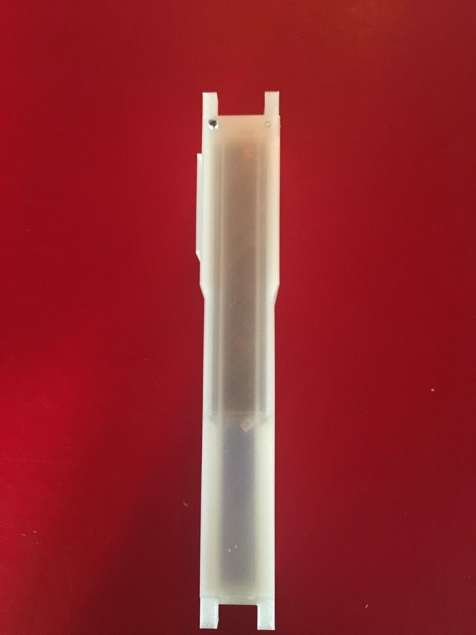
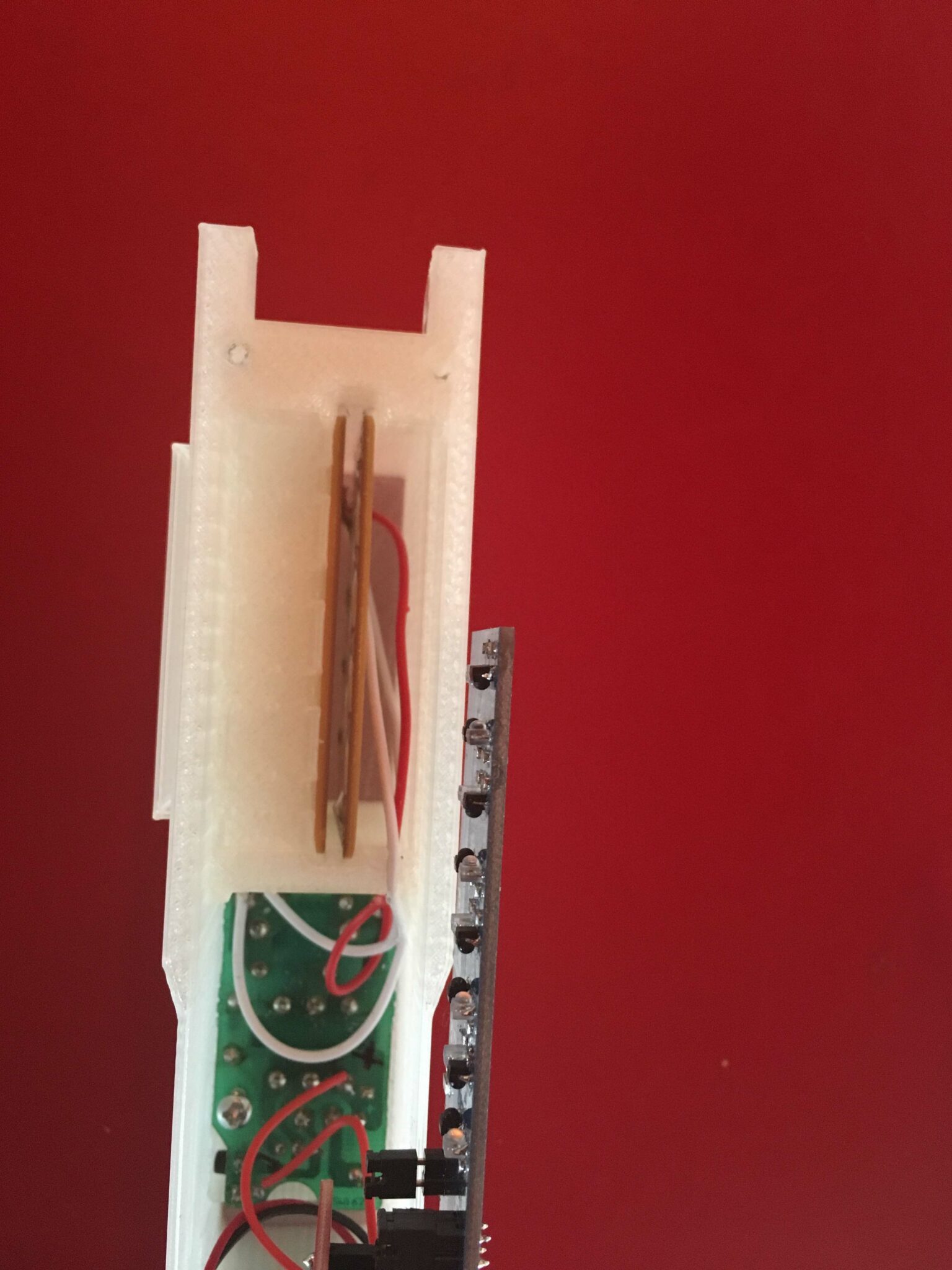
Here is the prototype in its final embodiment:
The Enclosure
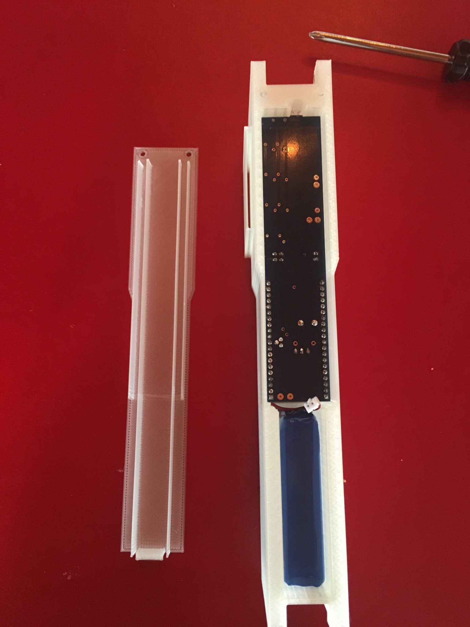
The enclosure was fabricated from PLA and serves several functions. In addition to replacing the side bar of a standard deep frame, and as a protective enclosure for the internal hardware, the enclosure also provides a shelter for the hive beetles to encourage them to gather near the trap entrances, or “gates”. If desired, the trap well can be baited to further entice SHB to enter the gates.
The Detection System
The detection system is comprised of pairs of Infrared emitters and detectors. There are four “gates” into the trap. Each gate contains two emitter-detector pairs. As the beetle passes into the gate, it sequentially breaks the beams of light, allowing the microcontroller to count the travel into and out of the trap. When the detection system logs a beetle entering the trap, the microcontroller activates the high-voltage system, allowing it to charge.
The High-Voltage Trap
This system begins charging when activated by the microcontroller, based on a triggering event. This helps to conserve power without compromising the effectiveness of the trap. It takes approximately 50ms to fully charge the system. The high voltage trap consists of a high-voltage step-up transformer, a 1µF 630V-rated Polypropylene (PP), Metallized Radial Film Capacitor, and two copper clad contact plates. The system delivers a 600V charge of sufficient power to convert a mass of water equivalent to the average mass of an SHB completely to steam, killing the beetle instantly.
The Power System
The power system design is constrained by physical geometry, commercial availability, and power consumption requirements. Under the current design constraints, the battery must fit inside the enclosure. The battery must be available off-the-shelf without custom requirements and should maximize the storage capability given the available size.
The selected battery was a 3.7V/6 Ah Lithium-Ion Rechargeable Battery. At the time it was the highest energy density battery in production. Without optimization, the prototype was able to run for 8 days of continuous operation while transmitting with the Wi-Fi radio. With the addition of an external solar panel and a switching regulator, the field life was extended by 1-2 days for each sunny day, sufficient for a two-week field trial without recharging. The provided 3.5 Watt solar panel is produced by Voltaic systems.
The Microcontroller
The core of the smart trap is the microcontroller, which provides the executive functions of the overall SHB Smart Trap device. The ESP32, by Espressiff Systems was selected as the microcontroller for this design, based on the following characteristics:
Hybrid Wi-Fi & Bluetooth Chip – ESP32 can perform as a complete standalone system or as a slave device to a host MCU, reducing communication stack overhead on the main application processor. ESP32 can interface with other systems to provide Wi-Fi and Bluetooth functionality through its SPI / SDIO or I2C / UART interfaces.
High Level of Integration – ESP32 is highly-integrated with in-built antenna switches, RF balun, power amplifier, low-noise receive amplifier, filters, and power management modules.
Ultra-Low Power Consumption – Engineered for mobile devices, wearable electronics and IoT applications, ESP32 achieves ultra-low power consumption with a combination of several types of proprietary software. ESP32 also includes state-of-the-art features, such as fine-grained clock gating, various power modes and dynamic power scaling.
Robust Design – ESP32 is capable of functioning reliably in industrial environments, with an operating temperature ranging from –40°C to +125°C. Powered by advanced calibration circuitries, ESP32 can dynamically remove external circuit imperfections and adapt to changes in external conditions.
Data-logging Webserver
The data-logging webserver was provided to record and display inbound data from the devices. A portion of the user interface is shown below for illustration

Field1 Chart: Net traffic count – every time SHB pass into the trap, this increments by one. If they leave without being zapped it decrements. However, the data is logged periodically, so if an SHB goes in and out once before the data is reported, no change will show up.
Field2 Chart: Zaps – every time the zapper is activated and discharges, this will increment. Ideally, this will directly correlate with the number of dead SHB in the trap.
Field3 Chart: Timeouts – if the zapper is activated, but does not discharge, this will increment. This should indicate how many SHB fully enter the trap but don’t make contact with the zapper surfaces.
Field3 Chart: Battery – this number directly correlates to the battery voltage. At 3250, the battery needs a charge.
The remaining charts are reserved for diagnostic flags and troubleshooting issues that are outside the intended user’s scope.
Electrical Schematics


PCB Design


